Engineering Notes: Morgan Chopper - Engineering Notes

Morgan Chopper Circuit Diagram

Block diagram of the proposed system fig. 2. chopper controlled dc Engineering notes: morgan chopper

First quadrant chopper Morgan technical and other topics blog: other morgan wiring diagrams Block diagram of the chopper circuit.

Engineering Notes: Jones chopper - Engineering notes

Four quadrant chopper or class-e chopper

Chopper quadrant

Morgan chopperChopper jones circuit diagram engineering notes Engineering notes: jones chopperChopper motor.

Engineering notes: morgan chopperChopper reactor Morgan chopperMorgan wiring diagram other topics technical.

Engineering Notes: Jones chopper - Engineering notes

Jones chopper circuit diagram

Chopper type quadrant first class circuit diagram planeJones chopper circuit diagram Wiring yamaha xs650 chopper 650 schematics elektrisch horn bobber g9 carts mikrora wiringgChopper morgan engineering notes waveforms.

Chopper morgan circuit diagram engineering notesChopper morgan circuit scr time saturable inductance reactor turn low higher due cost only Morgan chopper.

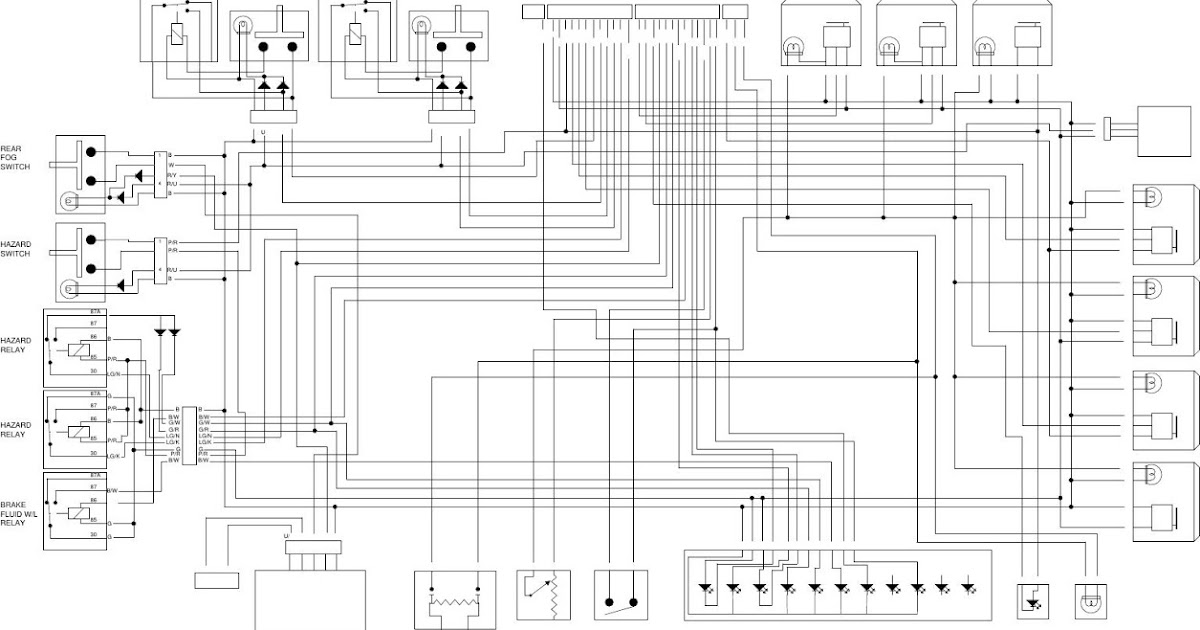
Jones Chopper Circuit Diagram

Morgan Technical and Other Topics Blog: Other Morgan Wiring Diagrams

Jones Chopper Circuit Diagram

Morgan Chopper
Morgan Chopper

Four Quadrant Chopper or Class-E Chopper - Electrical Concepts

Morgan Chopper | Electrical Revolution

Engineering Notes: Morgan Chopper - Engineering Notes

Morgan Chopper
Morgan Chopper

Block diagram of the Chopper circuit. | Download Scientific Diagram

Engineering Notes: Morgan Chopper - Engineering Notes

Block diagram of the proposed system Fig. 2. Chopper Controlled DC